This website uses cookies so that we can provide you with the best user experience possible. Cookie information is stored in your browser and performs functions such as recognising you when you return to our website and helping our team to understand which sections of the website you find most interesting and useful.
Vyhledávání
Tensile testing
The stress-strain curve of a material is determined experimentally using tensile testing. This is a static test, where a specimen is subjected to a slowly increasing stress in one direction, more precisely to a single axis stress – tensile stress, most commonly at room temperature. The test in principle continues until a complete failure of the structural integrity of a material, with the process enabling the determination of a number of significant properties which are crucial for the verification or characterization of the studied material.
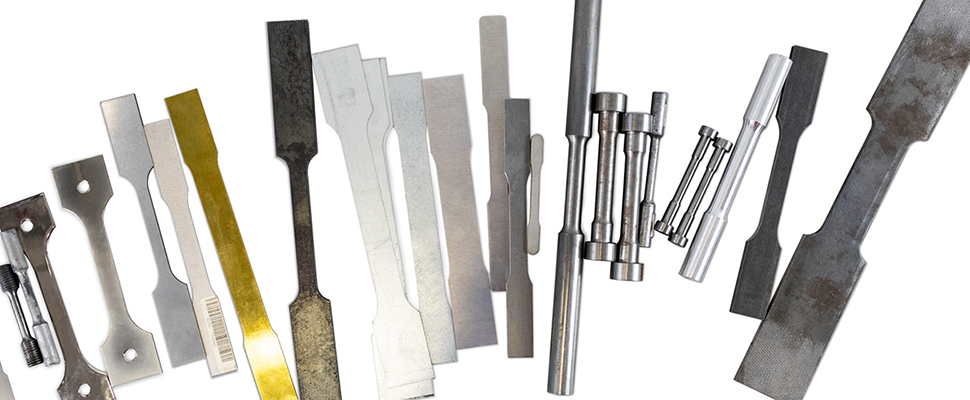
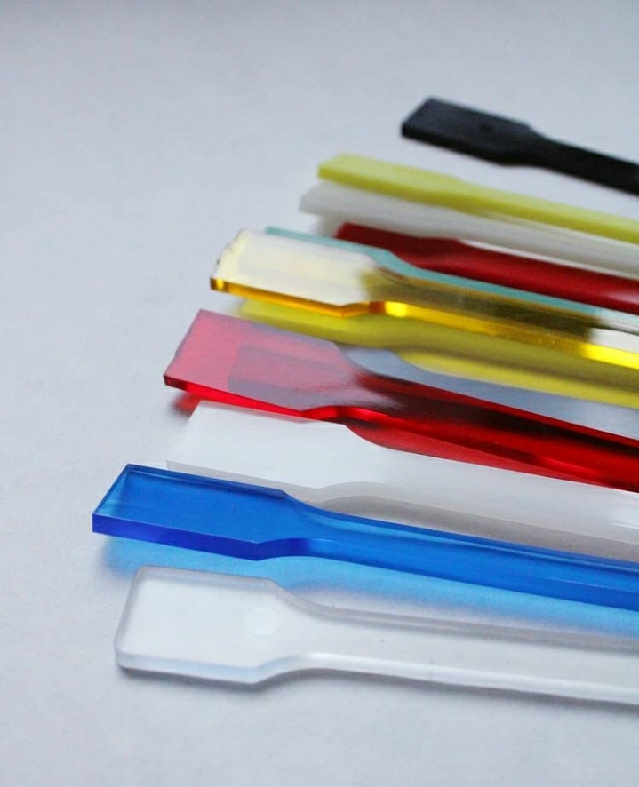
Specimen
The test is performed on test rods (specimen) of standardized dimensions or with rectangular cross-section. There are many standards laying down specimen dimensions, depending both on the studied material or production technology or specific ambient conditions (such as elevated temperature tensile testing).
Then, the specimen are clamped into a testing machine using jaws with different clamping mechanisms, depending on their type and design. We distinguish clamping jaws e.g. wedge jaws (self-locking), form-fit jaws, threaded jaws, pneumatic jaws etc. For this reason, it is necessary to adapt a part of the sample (the end of the test rod), by, for example, cutting a thread.
Clamping the test rod requires a careful attention. If, for example, the sample slips from the clamp during the test, this seriously complicates the assessment of the measured values, or even renders them impossible.
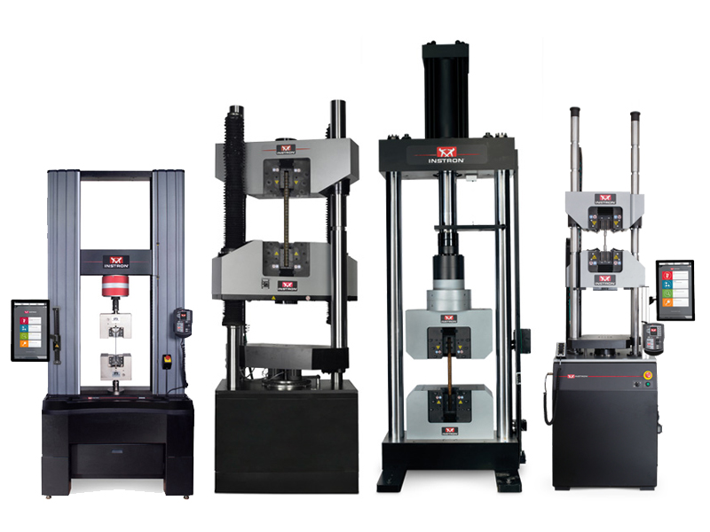
Testing instruments
The design of the testing machine is very versatile, which allows us to perform not only tensile testing, but also compression and bending testing. For individual types of tests, the machine needs to be rebuilt, that is, exchange jaws for different components, depending on the type of testing. Further, it is necessary to change the settings of the testing process in the software, which controls the machine during testing, to avoid any damage of the machine. Today, all testing machines are controlled by a software programme, which is delivered with the machine. The software also controls safety during a test, primarily using pre-set limits, which, if exceeded, immediately interrupt or stop the test; it also records any measured values.
Testing machines can also have different dimensions, overall designs, and drives (such electromechanical or hydraulic), as well as different maximum forces they can apply.
This also needs to be taken into account when designing sub-dimensions of a specimen.
The device consists of a rigid frame, in which there is a movable crosspiece. One of the jaws is located on this crossbar, while the other one is placed directly on the rigid frame of the machine. The movement of the crossbar is loading the sample clamped in the jaws.
During the test, a number of data is being recorded, the most important of which is the load force, acting on the sample, which is sensed with a dynamometer and recorded during the entire test. Another parameter, recorded throughout the test, is sample elongation, which can be measured by both the movement of the crossbar or using an extensometer. There are many types of extensometers, which differ according to their design and the sample elongation method. The most commonly used extensometers include the so called clip-on extensometer which is attached to the sample, using e.g. an elastic band, with the elongation of the sample subsequently measured based on the change in the opening angle of the extensometer arms. Other extensometers such as non-contact (laser, optical) can be used.
Tensile testing process
The progress of the tensile test is recorded on a tensile chart, showing the dependence of force (tension) on (relative) elongation of the specimen. We distinguish three types of tensile charts, working chart (dependence of force F on elongation ΔL), contractual chart (dependence of tension R on relative elongation ε, relative to the original dimensions of the sample) and real chart (dependence of real tension σ on real elongation φ, relative to real existing dimensions of the sample during the test).
The first stage of the tensile test shows the linear dependence of tension on relative elongation (according to Hooke’s law). Up to the proportionality limit, all deformations are elastic (reversible). This means that if we interrupted the test at this stage, the sample would resume its original shape.
The deformation is still elastic In the region between the proportionality limit and the yield strength, but the dependence of tension on elongation is no longer linear.
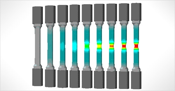
The plastic (irreversible) deformation of the material occurs when the yield strength is achieved. This deformation is homogeneous throughout the specimen volume up to the ultimate tensile strength.
Ultimate tensile strength is a maximum tension limit, at which the specimen deformation is still homogeneous.
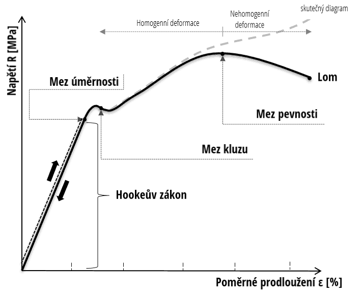
Subsequently, the deformation of the specimen occurs, i.e. non-homogeneous. The deformation is concentrated in one region; the tension declines, which, for some materials, may result in necking. This deformation continues until the total exhaustion of the plasticity of the material when the limit of structural integrity is exceeded, resulting in a fracture. At this point, the test is concluded.
Assessing the measured values
The deformation chart of the dependence of tension on the relative elongation of the tensile test bar gives us a number of important material characteristics. The most important ones include Young’s modulus of elasticity in tension, which can be determined as a standard of the linear part of the chart. Another important characteristic is the ultimate tensile strength, defined as the quotient of the maximum force exerted on the specimen and the cross-sectional area of the sample before the beginning of the test. Another key information is yield strength, which is a limit value for the occurrence of the plastic deformation. This limit, which is characterized by the diversion of the chart from linear development, is relatively very apparent and easily recognizable for some materials. For materials, where this is not the case, the so called proof strength was introduced, which corresponds to 0,2 % of a deformation.
In addition to the tensile chart alone, which provides a great deal of important information, it is possible to make an examination of the fracture area of the sample itself using light or electron microscopy.
Electron microscopy (SEM) can be used not only to assess the fracture area (fractography), but due to its combination with focused ion beam (FIB), it is possible to create a test specimen of severalfold smaller dimensions, enabling us to evaluate the mechanical properties of not only the material as a whole, but also to study directly the properties of a specific material phase.
For this type of testing, i.e. in-situ testing, which can be done using both the scanning (SEM) and the transmission electron microscope (TEM), it is necessary to have a corresponding equipment for the microscope.