This website uses cookies so that we can provide you with the best user experience possible. Cookie information is stored in your browser and performs functions such as recognising you when you return to our website and helping our team to understand which sections of the website you find most interesting and useful.
Vyhledávání
Meshing
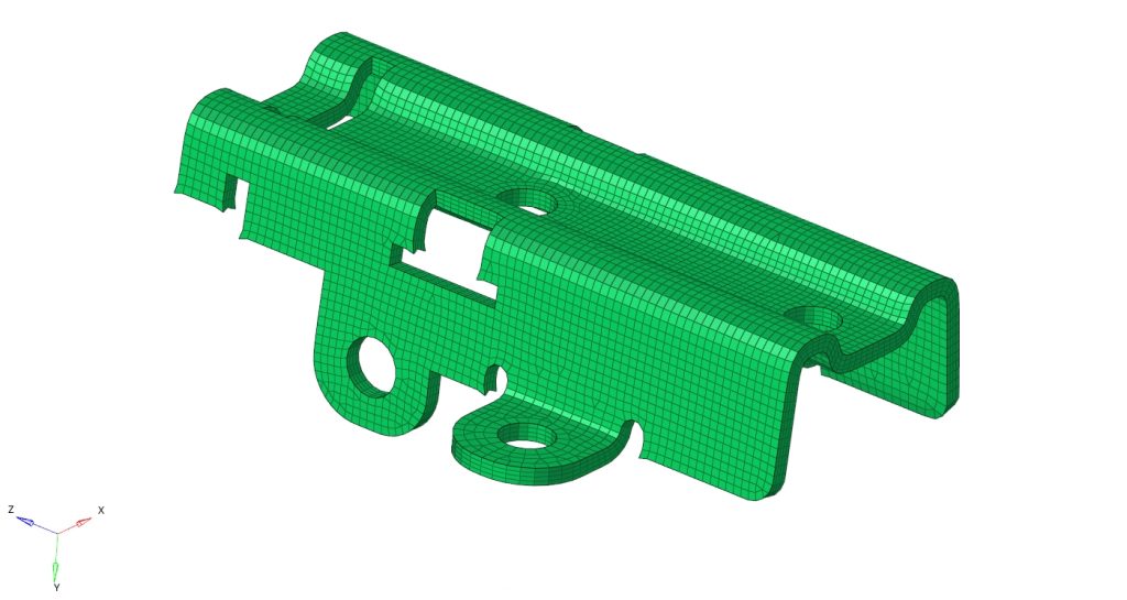
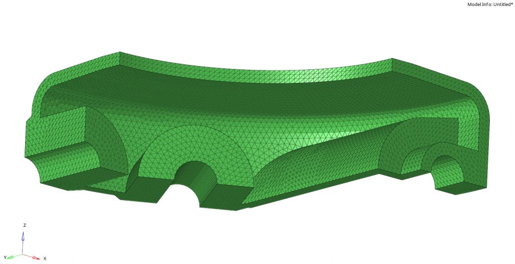
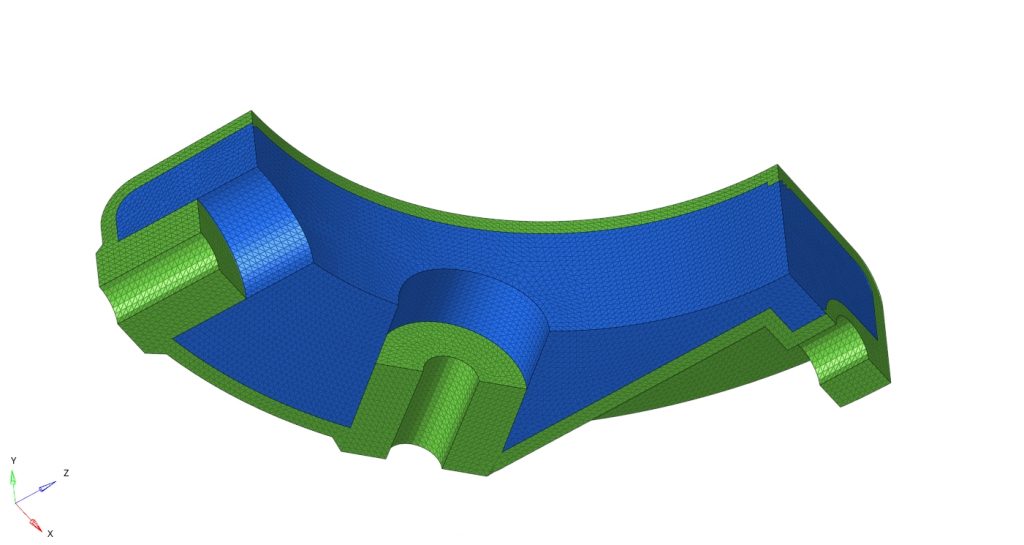
For performing an analysis or an FEM optimisation, it is necessary to create a mesh on a given work for the FEM. Its parameters, especially the size and mesh type, depend primarily on the shape of the mechanical part and the type of analysis. Generally, the FEM meshes can be divided into 1D (suitable, for example, for beams or pipes), 2D (suitable for sheet plate parts, thin-walled profiles etc.) and 3D (for castings or forgings). On a given work, elements, and interlinked nods are created, giving a discrete description of the part’s geometry. The majority of meshing tools can generate linear elements, as well as second order elements (quadratic) or P-elements (shape description using a higher-degree polynomial). It all depends on the type of task, and the capacities of the solver.
The software for generating mesh typically uses several algorithms simultaneously, enabling the user to choose the most suitable meshing topology. The user can influence element distribution and nod position to achieve the desired quality of the mesh. Mesh quality then directly influences the quality of the FEM analysis results. For checking mesh quality, a number of different criteria is available; most importantly, minimum and maximum dimensions of elements, then checking an element’s side size ratios; element tapering, collapsing etc. It also enables the verification of mesh integrity or the checking of element predetermination.